Sunday, August 28, 2011

Open Telecine: Lighting and Test Optics


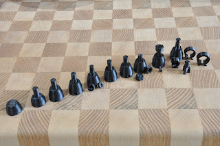
The following photos show progress on the Open Telecine hardware: to include: lighting mount, enlarged aperture, enlarged retaining spring, and partial body (just enough to hold light to aperture).

The light mount is specifically designed to hold a Luxeon Rebel LED (http://www.sparkfun.com/products/10179) 56 mm away from the film. The hollowed cone and wire guide was designed to reduce light pollution. A 2 mm hole was place along the axial shaft of the LED, to eliminate the reflections off the solder joints and produce a point source of light.

As shown in the photo, a temporary test optics was place between the aperture and camera CCD. This allows the team to determine what lighting, aperture and optical adjustments should be made. Some possible problems include: light blooming through the film sprocket holes, lighting cone too small to cover entire 8mm film, poor ability to focus, and diverging light (instead of converging light). It is known that a point source of light placed at the focal point will be converted into a collimated beam by the lens. Additionally, a positive or converging lens in air will focus a collimated beam travelling along the lens axis to a spot (known as the focal point) at a specific distance from the lens. This is what we need to convert the 8mm rectangle of diverging light into am adjustable rectangle (1-3mm) of converging light.

Any idea on how to improved the quality of the captured photo?

This post was created by using only open source hardware and software: CyanogenMod 7 (similar to stock Android or Windows Phone), Ubuntu (similar to Microsoft Windows and MacOS), gimp (similar to Adobe Photoshop), ReplicatorG, LibreCAD and OpenSCAD (simular to AutoCAD), and MakerBot.

Sunday, August 21, 2011

Open Telecine: Aperture


The remain physical components to be build for the Open Telecine are: aperture, lighting, optics (adjust wheel and cone), body, and film guide wheels. The part that was manufactured in this blog was the aperture. The images show the final aperture in pieces and assembled.

According to Wikipedia, "In optics, an aperture is a hole or an opening through which light travels. More specifically, the aperture of an optical system is the opening that determines the cone angle of a bundle of rays that come to a focus in the image plane. The aperture determines how collimated the admitted rays are, which is of great importance for the appearance at the image plane. If an aperture is narrow, then highly collimated rays are admitted, resulting in a sharp focus at the image plane. If an aperture is wide, then uncollimated rays are admitted, resulting in a sharp focus only for rays with a certain focal length. This means that a wide aperture results in an image that is sharp around what the lens is focusing on and blurred otherwise. The aperture also determines how many of the incoming rays are actually admitted and thus how much light reaches the image plane (the narrower the aperture, the darker the image for a given exposure time)."

The 8mm aperture was build in a small body that will compress the film between two planes: a fixed plane and a leaf spring. This allows the film to slide through with kinks and bumps (e.g. between the feeder film and film). The plastic grain is extruded to align parallel with the film, thus making a smoother contact surface. The current aperture is 8mm x 8mm, making it project the entire surface of the film. This include the sprocket holes and edges. The hopes are that the sprocket holes will help in detecting the film speed and frame position when using image processing (e.g. Canny edge detection).

Wednesday, August 17, 2011

Open Telecine and Mounts


The following parts have been created using OpenSCAD: motor mount, freewheel, freewheel mount, 100mm shaft, extended motor connector /w clip, and extended motor connector w/ thread.

The photo of the desktop shows the motor mount being build by using a 2D outline in LibreCAD, then extruding into 3D with OpenSCAD, and finishing additional customization using constructive solid geometry (http://en.wikipedia.org/wiki/Constructive_solid_geometry).

A flanged bushing was used for the freewheel and mount. The hopes are that this bushings will provide a small amount of friction, and keep the film tight. Second, it might serve as a way to eliminate the motor on the reel with film (i.e. not the uptake reel). The rewind function can still be achieved by swapping the two reels. The trade-off become lower cost and more work versus higher cost and less work.


This part was created by using only open source hardware and software: Ubuntu (similar to Microsoft Windows and MacOS), gimp (similar to Adobe Photoshop), ReplicatorG, LibreCAD and OpenSCAD (simular to AutoCAD), and MakerBot.

Saturday, August 13, 2011

Open Telecine and 8mm Film Spool


I assume, that in most cases, film will already be stored on a spool. However, not everyone using Open Telecine will have an uptake reel or extra reel. For those users who are short on a reel, an open source reel was developed.

As seen in the first photo, the reel is split into two halves, each with 6 segments. The segments are connected together using a dovetail joint, with 1.5mm protruding and recessed divots to lock them together.


Each half of the film is locked together (again with divots) using concentric cylinders, with the outer most cylinder holding the initial wrap of film. There is also a small gap in outer most reel to allow for an initial film lock.

The last photo, from OpenSCAD, shows an updated version that has holes to indicate the amount of film a reel contains, starting at 25m and ending in 150m. Thus, this 8mm film reel can hold approximation 150 meters of film. By experimentation, it appears that film lenght (L in m) is functionally determined by radius of film (R in m) and radius of spool wheel (S in m), L = (6500*PI*R*R)-(6500*PI*S*S). Thus, for our S=0.03 reel, R = SQRT(L+6500*PI*0.03*0.03)/(10*SQRT(65*pi)). No additional experimentation was performed on the final reel to determine accuracy. This will be conducted for when the electronics is connected, to allow the motor to do its job in reeling up the film.

Since the Open Telecine film reel differs in thickness from a commercial reel, the motor reel connectors will also need to be updated.


This part was created by using only open source hardware and software: Ubuntu (similar to Microsoft Windows and MacOS), gimp (similar to Adobe Photoshop), blender (similar to Autodesk Maya), ReplicatorG, LibreCAD and OpenSCAD (simular to AutoCAD), and MakerBot.

Wednesday, August 10, 2011

Open Telecine and 8mm Film spool Connectors

One of the ways to step through a sequence of frames in a film, is to connect the 8mm film spool to a stepper motor. The problem solved in this blog is the structural support material needed to convert a 5mm motor shaft to the slotted 8mm film spool.


The first approach used was to design 3D drawing of the spool connector in blender (blender.org), then use a MakerBot (makerbot.com) to fabricate the part. In the first photo (left to right), blender was used until an attempt was made to add threads to the top of the connector shaft. This was necessary in order to secure the film spool to the connector shaft with a nut. However, even though this problem can be solved in blender, I come to the realization that a computer-aided design (CAD) program would be more appropriate.

Starting on the 6th spool connector (first photo left-to-right), LibreCAD (librecad.org) and OpenSCAD (openscad.org) was used. To re-accomplish the same work from blender, it took 5 minutes to complete a 2D draft in LibreCAD, and 20 minutes in OpenSCAD. Each additional draft in OpenSCAD was exported to an .stl file (STL files describe only the surface geometry of a three dimensional object). ReplicatorG 0025 (replicat.org) was then used to convert each draft to g-code. G-code is the common name for the most widely used computer numerical control (CNC) programming language, and in my case, the MakerBot.

The second and third photographs show the completed product. Two spool connectors were generated: one with a threaded shaft and nut (secure but take longer), and the other with a notched shaft and clip (faster but less secure).


This part was created by using only open source hardware and software: Ubuntu (similar to Microsoft Windows and MacOS), gimp (similar to Adobe Photoshop), blender (similar to Autodesk Maya), ReplicatorG, LibreCAD and OpenSCAD (simular to AutoCAD), and MakerBot.


Wednesday, August 3, 2011

Open Telecine and MakerBot Thing-O-Matic


Being a special day for me, my loved one bought me a MakerBot Thing-O-Matic. The first print was a calabration cube. The second print, as show in the first photo, is a spool that will feed the ABS plastic thread into the heated extruder. The shown part is three pieces snapped together. The second photo shows the completed item. ReplicatorG v25 can be seen on the screen, which is producing gcode to control the stepper motor. The original purpose for the 3D printer is to manafacture parts needed to make an Open Telecine, which is scheduled to convert 60 spools of 8mm film!

This part was created by using only open source hardware and software: Ubuntu (similar to Microsoft Windows and MacOS), gimp (similar to Adobe Photoshop), ReplicatorG, and MakerBot.

Friday, July 22, 2011

Duty cycle and pulse-width modulation on the Arduino UNO with Linux


int PIN = 13;
float dutyCycle = .75; // between 0-1

void setup() {
pinMode(PIN, OUTPUT);
}

void loop() {
int state = 0;

while(1) {
if(state == 0) {
digitalWrite(PIN, LOW);
delay(1000 * (1-dutyCycle));
state = 1; }
else {
digitalWrite(PIN, HIGH);
delay(1000 * dutyCycle);
state = 0;
}
}
}

Tuesday, July 19, 2011

Square wave tutorial using Arduino UNO and Ubuntu/Linux

The following video was made as a tutorial on square waveform generation using an Arduino UNO and Ubuntu. It is a very basic video, and I hope to make another one soon on stepper motor controllers next.

The video was made with OpenShot Video Editor under Ubuntu Linux (similar to Microsoft Windows, Adobe products, or iMac).


int PIN = 13;

void setup() {
pinMode(PIN, OUTPUT);
}

void loop() {
int state = 0;

while(1) { if(state == 0) {
digitalWrite(PIN, LOW); state = 1;
}
else { digitalWrite(PIN, HIGH); state = 0;
}
delay(2000);
}

Tuesday, July 12, 2011

AOYUE 2702A+, SAC 305, and Throwing Star LAN Tap


The AOYUE 2702A+ arrived yesterday, which is a all-in-one digital hot air station with a soldering iron, a built-in smoke absorber, a desoldering gun, and a desoldering pen. Kelly found a great spot in the house where we immediately set up a workbench for electronics, jewelry crafting, and other similar manufacturing projects.

Since I had never soldered before, the first task was to assemble a DYI project called "Throwing Star LAN Tap". You can read more about this project at Michael Ossmann blog. The solder of choice for this task was the SAC 305, which is a lead free with a melting range of 217-221°C. In the photo, each of the four Ethernet connectors were soldered in counterclockwise fashion, starting at the 12-o'clock position.

Thursday, June 30, 2011

Persephone: The Goddess of Spring Growth

The following vase is a combination of two techniques, hand-building and wheel throwing. The face, hair, vines, and flowers are all hand-built using NO molds or visuals. The vase was wheel thrown. The clay used to create the piece is called Ash. The glaze on the vines and flowers is called Rutile. The vase was inspired by the changing season and our connection to mother earth. The serenity and beauty which is within us all can be reflected in the art which we create and surround ourselves with. My art is a piece of me and I hold it very dear to my heart.

Sunday, June 26, 2011

Cocoon Flower/Spice Planter

The following piece, approx. 2'5" long, was inspired due to a mistake in my throwing. The original vase was a bit crooked, therefore, I took it off the wheel and in a moment of frustration tossed it on the table beside me. However, in that moment, I saw a new shape from that haphazard mistake. It resembled the bulbous portion of a cocoon, the part which is below the attachment to the tree. I then decided to remove the top and bottom portion of the vase and replace it with smoothed hand built coils, in order for the final cocoon shape to have an organic resemblance to a real cocoon. The final steps included cutting a large hole on the top, thickening the lip for sturdiness, and cutting circular holes on the bottom for drainage. I am excited to see the final fired piece which will take some time because I am allowing it to dry slowly, in order to prevent cracking.

Photos are generally taken with a Nikon D90 or Sprint HTC Evo running CyanogenMod (simular to Windows mobile cell phone and iPhone). No cell phone service or AppStore applications were used, but DSL/cable modem internet service was used.

Tuesday, June 21, 2011

OpenTelecine, OpenCV, image processing


The two biggest challenges to overcome in the OpenTelecine project are optics and image processing. In previous blogs, we discussed some accomplishments in image processing for the rectangular geometries found in 8mm film frames and film spool holes. In this blog, we shall discuss the failures and upcoming challenges in configuring the camera and OpenTelecine optics to illuminate and capture 8mm frames.

The first image is a prototype of a projector using a SparkFun cardboard box, Petzl LED headlight, and an existing projector optical focus. An unusual attribute of this prototype is the lack of a well defined aperture. In optics, an aperture is a hole or an opening through which light travels. More specifically, the aperture of an optical system is the opening that determines the cone angle of a bundle of rays that come to a focus in the image plane. In our case, the aperture was cut out to be a large rectangular hole that spans multiple 8mm frames. Another unusual characteristic is that the film rests on a adjustable back-plane. This allows for the projector to have two optical parameters to adjust: the optical focus and the distance to the back-plane.


The prototype projector was set up in a dark room to project the 8mm film on a whiteboard. A Nikon D90 camera was set off to the side and capture a 10 second exposure of this image. Notice the imperfection in this photo, where the center spool hole is in perfect focus, whereas the left and right spool holes are not. Another unexpected discovery is that the images smear and streak off between frames, which is caused by the mechanical shutter and film transition. This is solved in practice by reducing the aperture size. 8mm film cameras generally have larger apertures then the projector, which causes a projector to display only a subset of each original frame. Striving to capture the maximum available frame in the OpenTelecine will be difficult because the frames will not have perfectly shaped rectangular frames and spool holes. The top of each frame will be smeared and streaked, whereas the spool holes are rounded rectangles.


Instead of capturing the film off the whiteboard, the camera and projector were placed inline to face each other directly. Notice that the images captured by using this approach are completely and totally unacceptable. Is this project doomed to fail?

Reflection, refraction, and chromatic dispersion are well understood, and there are precise mathematical solutions to this problem. My next attempt will come by a recommendation, which is to place the camera and project perpendicular to each, with a mirror between them at a 45 degree angle.

The project currently uses Ubuntu 11.04 (simular to Microsoft Windows), OpenCV, gimp (similar to Adobe), GNU gcc (similar to Microsoft .NET), and Eclipse. Photos are generally taken with a Nikon D90 or Sprint HTC Evo running CyanogenMod (simular to Windows mobile cell phone and iPhone).

Saturday, June 18, 2011

Open Telecine, OpenCV, image processing


"This is the second post about an attempt to make an open source telecine. Telecine is the process of transferring motion picture film into video form. The preliminary goal of this project is currently limited to converting 8mm film to DVD using a digital camera, while levering other open source projects. Telecine has had much success in using flatbed scanners and ones that record from modified film projectors. The frame-by-frame projector use by this project will be built from scratch, by using: two stepper motors, an arduino board, an EasyDriver (from SparkFun), a MakerBot for printing 3D components, a LEDs, and optics. The software to convert the images into a movie is yet to be determined, but here is an attempt."

The first image processing restrictions that was added (to identify rectangles with the desired proprieties) is the angle off the X/Y axis. 8mm film possesses two desired rectangular geometries, a picture frames and the spool holes. Since the project will capture all images (in strictly a vertical or horizontal orientation), additional code was added (to the OpenCV example) to only identify horizontal and vertical rectangles. In the first set of images, notice the tolerance of rectangles up to a 2.5 degree from the horizontal axis, where the 15 degree rectangle was ignored.


A second image processing restrictions that was added (to identify rectangles with the desired proprieties) is the X to Y proportion. Some of today's media comes in a 16:9 or 4:3 rectangular format, whereas 8mm has it's own ratios. The next set of images show the acceptance of rectangles with the ratios possessed by a 8mm picture frame and the spool hole.

The project currently uses Ubuntu 11.04 (simular to Microsoft Windows), OpenCV, GNU gcc, and Eclipse. The photo of the pottery vase was taken with an Sprint HTC Evo (simular to iPhone).

Thursday, June 16, 2011

Open Telecine, OpenCV, image processing


This is the first post about an attempt to make an open source telecine. Telecine is the process of transferring motion picture film into video form. The preliminary goal of this project is currently limited to converting 8mm film to DVD using a digital camera, while levering other open source projects. Telecine has had much success in using flatbed scanners and ones that record from modifyed film projectors. The frame-by-frame projector use by this project will be built from scratch, by using: two stepper motors, an arduino board, an EasyDriver (from SparkFun), a MakerBot for printing 3D components, a LEDs, and optics. The software to convert the images into a movie is yet to be determined, but here is the first attempt.

The first set of images are a mockup of frames being capture and processed to determined the film spool holes. The 8mm spool holes need to be determined in order to perform cropping correctly, and to uniquely identify each frame. The green squares were automatically identified by image processing. An example (e.g. squares.cpp) contained within OpenCV was modified to enhance the discovery of rectangles with greater accuracy. The image processing is as follows: pyramid scaling (for smoothing imaging and filtering out some noise), Canny algorithm (for edge detection), initial contours detection, Douglas-Peucker algorithm (for reducing the number of points in a curve), and finally rectangle detection (for eliminating other types of polygons). The next task is to add code that will only detect rectangles with the correct proportions for a 8mm spool hole.


The second set of images are from Flatbed Scanner Digital Telecine (FSDT) to give a more realistic test. Notice that the image processing failed to detect one of the spool hole. Near perfection is paramount, because of the number of frames contained on large spools of film.

The project currently uses Ubuntu 11.04 (simular to Microsoft Windows), OpenCV, GNU gcc, and Eclipse. The photo of the pottery vase was taken with an Sprint HTC Evo (simular to iPhone).

Wednesday, June 15, 2011

Shipping, Boulder hotels, and High Fructose Corn Syrup

Today I looked at my shipping tracker, which show a product that was purchased in Boulder Colorado (just 150 miles from Colorado Springs with nice hotels) has taken at least 6 days to get to my house. Also reading about High Fructose Corn Syrup, from another blog link.

Cerritos, CA, United States 06/14/2011 12:40 A.M. Departure Scan Cerritos, CA, United States 06/13/2011 2:12 P.M. Multiple errors exist in the address label. UPS is attempting to determine the correct information to complete delivery. / The address has been corrected. The delivery has been rescheduled. 06/13/2011 12:13 P.M. Incorrect routing at UPS facility. 06/13/2011 6:54 A.M. Out For Delivery Cerritos, CA, United States 06/10/2011 4:32 P.M. Arrival Scan Salt Lake City, UT, United States 06/10/2011 1:08 A.M. Departure Scan Salt Lake City, UT, United States 06/09/2011 3:02 P.M. Arrival Scan Commerce City, CO, United States 06/09/2011 6:25 A.M. Departure Scan Commerce City, CO, United States 06/08/2011 10:30 P.M. Arrival Scan Boulder, CO, United States 06/08/2011 8:11 P.M. Departure Scan 06/08/2011 6:56 P.M. Origin Scan United States 06/08/2011 6:40 P.M. Order Processed: Ready for UPS

Tuesday, June 14, 2011

Sculpted Face taken with a cell phone


This is a hand sculpted face attached to wheel thrown vase, with decorative handbuilt butterflies, which will eventually adorn the entire vase in a whirlwind pattern. These images were taken in Colorado Springs with an Sprint cell phone running Android/Cyanongen Mod, which is not a Windows Phone or an Apple iPhone. The images where reduced with Ubuntu and Gimp, which is not Microsoft Windows or Apple laptop. The mobile phone resolution is 8MP.

Sunday, June 12, 2011

Bicycle commute with Burley Nomad trailer and Boxer in Colorado Springs

Bicycle commute with trailer and Boxer in Colorado Springs. Zoey, the Boxer, rides in the cart when tired. It usually takes Zoey 10 miles on a hot day before she is ready to ride in the cart. The cart is a Burley Nomad, and the bicycles are Specialized. Watch the Video here!

Saturday, June 11, 2011

Art and Cell Phones

A little poem I wrote for my followers. Has cell phone design been influenced by closed composition? Due to the appearance of closed spatial composition, the artist reflected a desire for no interaction or a deep sense of emotion, but instead wanted a fixed ornate object much like classical Greek sculptures. Which is implied in the strict vertical lines, which are seen from knee to foot and hip to head. At the top of a phone screen, there is no implication of movement or diagonal lines to suggest forward action. A phone is fixed in a moment, which seems to have no emotional output. Compared to a woman, she appears serene with a slight smile suggesting no emotion. Every part of her body is firmly planted and aligned, with makeup. In this sense, smart phones and ladies share common characteristic.

Thursday, June 9, 2011

Art Sculpture Analysis

The Trailblazer is realistic but also has a touch of idealism added into its conceptualism.
When viewing the piece one can see the muscles and facial expression which suggests realism . Also the muscles are well defined creating shadow and intensity. The face is at piece with a slight smile to welcome you to look all around her. She is standing as most bicyclist would when at a halt, with one foot on the peddle and the other planted firmly on the ground. She is gazing forward as if frozen in time. The woman lacked any deformities or irregularities, which was the point of the piece considering it was to signify an idealistic view of a strong woman. Even though the texture is rough due to the realistic folds in her her shirt and waviness of her hair, she remains very smooth throughout. The tires on the bicycle are also rough but the rest is smooth just like her muscles and skin. She has no movement or interaction in plan, she is paused in a moment. Which draws me to the conclusion that the Trailblazer is closed spatial composition.