Sunday, August 28, 2011

Open Telecine: Lighting and Test Optics


The following photos show progress on the Open Telecine hardware: to include: lighting mount, enlarged aperture, enlarged retaining spring, and partial body (just enough to hold light to aperture).

The light mount is specifically designed to hold a Luxeon Rebel LED (http://www.sparkfun.com/products/10179) 56 mm away from the film. The hollowed cone and wire guide was designed to reduce light pollution. A 2 mm hole was place along the axial shaft of the LED, to eliminate the reflections off the solder joints and produce a point source of light.

As shown in the photo, a temporary test optics was place between the aperture and camera CCD. This allows the team to determine what lighting, aperture and optical adjustments should be made. Some possible problems include: light blooming through the film sprocket holes, lighting cone too small to cover entire 8mm film, poor ability to focus, and diverging light (instead of converging light). It is known that a point source of light placed at the focal point will be converted into a collimated beam by the lens. Additionally, a positive or converging lens in air will focus a collimated beam travelling along the lens axis to a spot (known as the focal point) at a specific distance from the lens. This is what we need to convert the 8mm rectangle of diverging light into am adjustable rectangle (1-3mm) of converging light.

Any idea on how to improved the quality of the captured photo?

This post was created by using only open source hardware and software: CyanogenMod 7 (similar to stock Android or Windows Phone), Ubuntu (similar to Microsoft Windows and MacOS), gimp (similar to Adobe Photoshop), ReplicatorG, LibreCAD and OpenSCAD (simular to AutoCAD), and MakerBot.

Sunday, August 21, 2011

Open Telecine: Aperture


The remain physical components to be build for the Open Telecine are: aperture, lighting, optics (adjust wheel and cone), body, and film guide wheels. The part that was manufactured in this blog was the aperture. The images show the final aperture in pieces and assembled.

According to Wikipedia, "In optics, an aperture is a hole or an opening through which light travels. More specifically, the aperture of an optical system is the opening that determines the cone angle of a bundle of rays that come to a focus in the image plane. The aperture determines how collimated the admitted rays are, which is of great importance for the appearance at the image plane. If an aperture is narrow, then highly collimated rays are admitted, resulting in a sharp focus at the image plane. If an aperture is wide, then uncollimated rays are admitted, resulting in a sharp focus only for rays with a certain focal length. This means that a wide aperture results in an image that is sharp around what the lens is focusing on and blurred otherwise. The aperture also determines how many of the incoming rays are actually admitted and thus how much light reaches the image plane (the narrower the aperture, the darker the image for a given exposure time)."

The 8mm aperture was build in a small body that will compress the film between two planes: a fixed plane and a leaf spring. This allows the film to slide through with kinks and bumps (e.g. between the feeder film and film). The plastic grain is extruded to align parallel with the film, thus making a smoother contact surface. The current aperture is 8mm x 8mm, making it project the entire surface of the film. This include the sprocket holes and edges. The hopes are that the sprocket holes will help in detecting the film speed and frame position when using image processing (e.g. Canny edge detection).

Wednesday, August 17, 2011

Open Telecine and Mounts


The following parts have been created using OpenSCAD: motor mount, freewheel, freewheel mount, 100mm shaft, extended motor connector /w clip, and extended motor connector w/ thread.

The photo of the desktop shows the motor mount being build by using a 2D outline in LibreCAD, then extruding into 3D with OpenSCAD, and finishing additional customization using constructive solid geometry (http://en.wikipedia.org/wiki/Constructive_solid_geometry).

A flanged bushing was used for the freewheel and mount. The hopes are that this bushings will provide a small amount of friction, and keep the film tight. Second, it might serve as a way to eliminate the motor on the reel with film (i.e. not the uptake reel). The rewind function can still be achieved by swapping the two reels. The trade-off become lower cost and more work versus higher cost and less work.


This part was created by using only open source hardware and software: Ubuntu (similar to Microsoft Windows and MacOS), gimp (similar to Adobe Photoshop), ReplicatorG, LibreCAD and OpenSCAD (simular to AutoCAD), and MakerBot.

Saturday, August 13, 2011

Open Telecine and 8mm Film Spool


I assume, that in most cases, film will already be stored on a spool. However, not everyone using Open Telecine will have an uptake reel or extra reel. For those users who are short on a reel, an open source reel was developed.

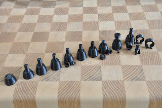
As seen in the first photo, the reel is split into two halves, each with 6 segments. The segments are connected together using a dovetail joint, with 1.5mm protruding and recessed divots to lock them together.


Each half of the film is locked together (again with divots) using concentric cylinders, with the outer most cylinder holding the initial wrap of film. There is also a small gap in outer most reel to allow for an initial film lock.

The last photo, from OpenSCAD, shows an updated version that has holes to indicate the amount of film a reel contains, starting at 25m and ending in 150m. Thus, this 8mm film reel can hold approximation 150 meters of film. By experimentation, it appears that film lenght (L in m) is functionally determined by radius of film (R in m) and radius of spool wheel (S in m), L = (6500*PI*R*R)-(6500*PI*S*S). Thus, for our S=0.03 reel, R = SQRT(L+6500*PI*0.03*0.03)/(10*SQRT(65*pi)). No additional experimentation was performed on the final reel to determine accuracy. This will be conducted for when the electronics is connected, to allow the motor to do its job in reeling up the film.

Since the Open Telecine film reel differs in thickness from a commercial reel, the motor reel connectors will also need to be updated.


This part was created by using only open source hardware and software: Ubuntu (similar to Microsoft Windows and MacOS), gimp (similar to Adobe Photoshop), blender (similar to Autodesk Maya), ReplicatorG, LibreCAD and OpenSCAD (simular to AutoCAD), and MakerBot.

Wednesday, August 10, 2011

Open Telecine and 8mm Film spool Connectors

One of the ways to step through a sequence of frames in a film, is to connect the 8mm film spool to a stepper motor. The problem solved in this blog is the structural support material needed to convert a 5mm motor shaft to the slotted 8mm film spool.


The first approach used was to design 3D drawing of the spool connector in blender (blender.org), then use a MakerBot (makerbot.com) to fabricate the part. In the first photo (left to right), blender was used until an attempt was made to add threads to the top of the connector shaft. This was necessary in order to secure the film spool to the connector shaft with a nut. However, even though this problem can be solved in blender, I come to the realization that a computer-aided design (CAD) program would be more appropriate.

Starting on the 6th spool connector (first photo left-to-right), LibreCAD (librecad.org) and OpenSCAD (openscad.org) was used. To re-accomplish the same work from blender, it took 5 minutes to complete a 2D draft in LibreCAD, and 20 minutes in OpenSCAD. Each additional draft in OpenSCAD was exported to an .stl file (STL files describe only the surface geometry of a three dimensional object). ReplicatorG 0025 (replicat.org) was then used to convert each draft to g-code. G-code is the common name for the most widely used computer numerical control (CNC) programming language, and in my case, the MakerBot.

The second and third photographs show the completed product. Two spool connectors were generated: one with a threaded shaft and nut (secure but take longer), and the other with a notched shaft and clip (faster but less secure).


This part was created by using only open source hardware and software: Ubuntu (similar to Microsoft Windows and MacOS), gimp (similar to Adobe Photoshop), blender (similar to Autodesk Maya), ReplicatorG, LibreCAD and OpenSCAD (simular to AutoCAD), and MakerBot.


Wednesday, August 3, 2011

Open Telecine and MakerBot Thing-O-Matic


Being a special day for me, my loved one bought me a MakerBot Thing-O-Matic. The first print was a calabration cube. The second print, as show in the first photo, is a spool that will feed the ABS plastic thread into the heated extruder. The shown part is three pieces snapped together. The second photo shows the completed item. ReplicatorG v25 can be seen on the screen, which is producing gcode to control the stepper motor. The original purpose for the 3D printer is to manafacture parts needed to make an Open Telecine, which is scheduled to convert 60 spools of 8mm film!

This part was created by using only open source hardware and software: Ubuntu (similar to Microsoft Windows and MacOS), gimp (similar to Adobe Photoshop), ReplicatorG, and MakerBot.

Friday, July 22, 2011

Duty cycle and pulse-width modulation on the Arduino UNO with Linux


int PIN = 13;
float dutyCycle = .75; // between 0-1

void setup() {
pinMode(PIN, OUTPUT);
}

void loop() {
int state = 0;

while(1) {
if(state == 0) {
digitalWrite(PIN, LOW);
delay(1000 * (1-dutyCycle));
state = 1; }
else {
digitalWrite(PIN, HIGH);
delay(1000 * dutyCycle);
state = 0;
}
}
}